Interface alignment
Select protected RF output or an integrated receiver path.
UGV resilient PNT
Maintain trusted positioning and timing when autonomous ground systems encounter intentional or unintentional RF interference.
Select protected RF output or an integrated receiver path.
Scale simultaneous nulling to the expected environment.
Confirm mounting, sealing, shock, vibration and temperature requirements.
UGV resilient navigation combines a protected GNSS signal path with integrity monitoring, independent vehicle sensors, defined degraded modes and tested recovery. A CRPA anti-jam front end can improve GNSS availability, but it does not replace INS, odometry, perception or host-system decision logic.
| Integration area | Buyer decision | Evidence to request |
|---|---|---|
| Protected GNSS front end | Constellations, bands, receiver path and required null capacity | Waveform, input level, geometry, protected bands and receiver-output result |
| Vehicle sensor stack | INS, wheel odometry, LiDAR, camera, map or other available inputs | Update rates, error behavior, alignment and cross-check logic |
| Integrity response | When the system warns, rejects GNSS or enters degraded mode | Thresholds, alert latency, logs and host-controller action |
| Installation | Array location, ground plane, cabling, nearby emitters and enclosure | Platform drawing, EMC review and representative installation check |
| Recovery | How trusted navigation is restored after interference clears | Reacquisition criteria, transition behavior and repeated test records |
Protected GNSS is one layer of a resilient navigation architecture, not a substitute for vehicle-level sensor fusion. The NIST Foundational PNT Profile frames responsible PNT use across identification, protection, detection, response and recovery. Use the NOVA resilient-PNT guide to define the system boundary and the testing framework to convert it into measurable acceptance criteria.
| Model | Published starting point | Protected bands | Mass and power | Anti-spoof |
|---|---|---|---|---|
| NOVA-D8 | 8-channel; three interference directions | B1 / B3 / L1 / E1 | ≤500 g; ≤17 W | No |
| NOVA-D8X | 8-channel; three interference directions | B1 / L1 / E1; B3, L5 or L2 second-band option | ≤500 g; ≤17 W | No |
| NOVA-H8 | 8 elements; seven interference directions | L1 / G1 | ≤720 g; ≤19 W | No |
| NOVA-AS16 | 16 elements; fifteen interference directions | B1 / L1 / E1 | ≤3.0 kg; ≤40 W | Yes |
Published values describe standard configurations, not guaranteed vehicle-level results. Confirm the selected product, receiver interface, environmental requirements and acceptance conditions in the quotation.
A CRPA front end can reduce interference before it reaches the GNSS receiver, improving satellite-signal availability. The autonomy system should still monitor integrity and combine GNSS with appropriate inertial, odometry, perception or map-based inputs.
No. A CRPA protects the GNSS signal path; an INS and other vehicle sensors provide independent motion or environment information. Their interfaces, trust logic and degraded-mode behavior must be designed and tested as one system.
Some configurations provide a protected RF output for a compatible external receiver, while others include a receiver or use a different host interface. Confirm bands, RF level, impedance, connector, power path, output format and receiver behavior before treating any configuration as a retrofit.
Define the interference or signal-loss condition, system boundary, monitored GNSS and sensor outputs, alert threshold, degraded-mode action and recovery criteria. Use an authorized controlled-RF setup for repeatability, then verify mounting, cabling, self-interference and host-controller behavior on a representative vehicle.
Provide the vehicle type, GNSS receiver and bands, navigation-sensor stack, protected-RF or integrated interface, mounting and cable constraints, nearby emitters, voltage and power budget, environmental needs and measurable acceptance scenario.
The vehicle can compare GNSS position, velocity and timing behavior with independent motion and environment evidence such as IMU output, wheel odometry, LiDAR, cameras and map constraints. A mismatch can support warning or rejection logic, but thresholds, alert latency, degraded-mode action and recovery must be designed and validated for the complete vehicle system rather than assumed from one sensor.
Use these models as an engineering shortlist, not as a substitute for a configuration review.
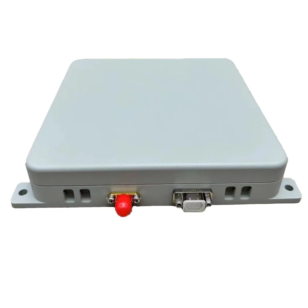
Dual-Frequency Resilient PNT Terminal
Enhanced Dual-Frequency Resilient PNT Terminal
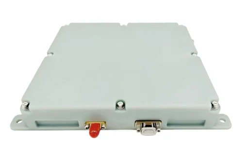
8-Element Dual-System Resilient PNT Terminal
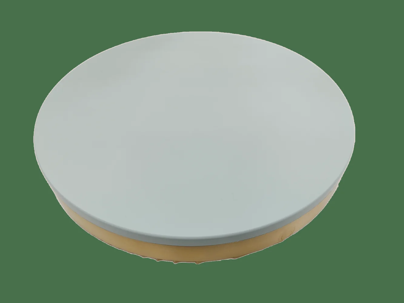
16-Element Anti-Jam + Anti-Spoof PNT Terminal
Next step
Share platform, protected bands, interfaces and project timing. Zhiyunlai will confirm a suitable starting configuration and the information needed for validation.