Start with SWaP
Match array scale to mass, diameter, voltage and available power.
UAV GNSS anti-jamming
Protect navigation availability on unmanned aircraft without redesigning the complete flight-navigation stack.
Match array scale to mass, diameter, voltage and available power.
Define the GNSS constellations and frequencies used by the existing receiver.
Account for mounting, cable loss, self-interference and acceptance conditions.
A UAV GNSS anti-jamming system should be selected by the protected bands, receiver path, required simultaneous interference directions and the aircraft's size, weight and power limits. Choose the smallest documented configuration that fits the platform, then verify it under defined controlled-RF and representative-installation conditions.
| Selection input | What to define | Why it matters |
|---|---|---|
| Airframe and mission | Fixed-wing, multirotor or another authorized unmanned platform | Sets the installation, dynamics and continuity context |
| SWaP envelope | Maximum dimensions, mass, voltage and power | Narrows the array and processing options before performance comparison |
| GNSS signal path | Constellations, frequencies, receiver and protected-RF or integrated path | Prevents selecting coverage or interfaces that do not match the host system |
| Interference requirement | Waveform, power, geometry and simultaneous directions | Gives suppression and null-count figures an acceptance context |
| Platform integration | Mounting, ground plane, cable loss, nearby emitters and environment | Accounts for airframe effects that a bench specification cannot show |
For weight-critical platforms, compare the NOVA-M46 and NOVA-S65. For more protected bands, null capacity or anti-spoof requirements, use the full shortlist below. Review the supplied platform demonstration and acceptance framework before fixing the final configuration.
If the UAV must continue navigating after the complete protected GNSS signal set becomes unusable, define complementary navigation and transition behavior at system level. The NOVA resilient-PNT architecture guide explains how protected GNSS, integrity monitoring and independent navigation layers fit together.
| Model | Published starting point | Protected bands / systems | Mass and power | Anti-spoof |
|---|---|---|---|---|
| NOVA-M46 | Micro terminal; one interference direction | BDS / GPS / GLONASS / Galileo | 40 g; ≤60 mA @ 5 V | No |
| NOVA-S65 | 4-channel; three interference directions | B1 / L1 / E1 | ≤130 g; ≤6 W | No |
| NOVA-D8X | 8-channel; three interference directions | B1 / L1 / E1; B3, L5 or L2 second-band option | ≤500 g; ≤17 W | No |
| NOVA-AS4 | 4-element dual protection; three interference directions | B1 / L1 / E1 | ≤520 g; ≤13 W | Yes |
Published values describe standard configurations, not guaranteed platform results. Confirm the selected option, receiver interface and acceptance conditions in the quotation. For CRPA system-boundary background, review the U.S. Coast Guard GPS user-equipment antenna guidance and the NOVA CRPA integration guide.
Start with the aircraft mass and power budget, protected GNSS constellations and frequencies, receiver or protected-RF interface, required simultaneous-null capacity, installation envelope and whether anti-spoof protection is also required.
No. More antenna elements can support more spatial information and null directions, but they also affect size, mass, power, mounting and cost. The correct array is the smallest configuration that meets the defined interference and acceptance scenario.
Some configurations can provide a protected RF path to a compatible external receiver, while others use an integrated receiver or different host interface. Confirm the protected bands, RF level, impedance, connector, power path and receiver compatibility before treating any terminal as a retrofit.
Link the quoted hardware and software configuration to a defined GNSS signal condition, interference waveform, input level, source geometry and measurement point. Record receiver or host outputs in an authorized controlled-RF setup, then check mounting, cabling and self-interference on a representative platform.
Provide the UAV type, payload and power limits, GNSS receiver, protected bands, available mounting area, connector and cable path, nearby emitters, environmental requirements, prototype quantity and measurable acceptance criteria.
Not by itself. A CRPA anti-jam front end can improve GNSS signal availability by reducing interference reaching the receiver, but it cannot create a satellite signal when the complete protected signal set is unavailable. Continued navigation then depends on the UAV's independently designed and tested inertial, visual, radar, odometry, map-based or other complementary navigation layers.
Use these models as an engineering shortlist, not as a substitute for a configuration review.
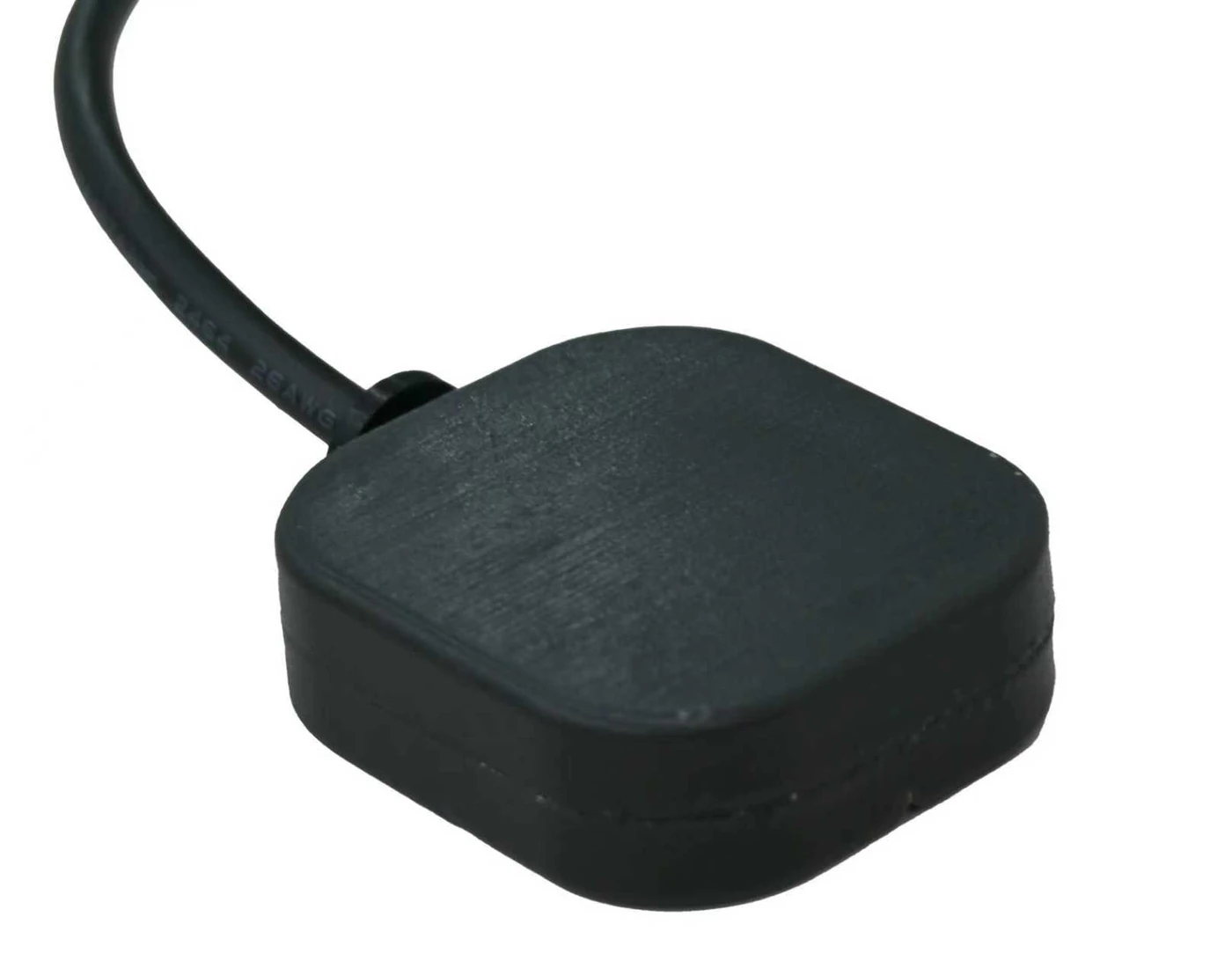
Ultra-Compact Resilient PNT Terminal
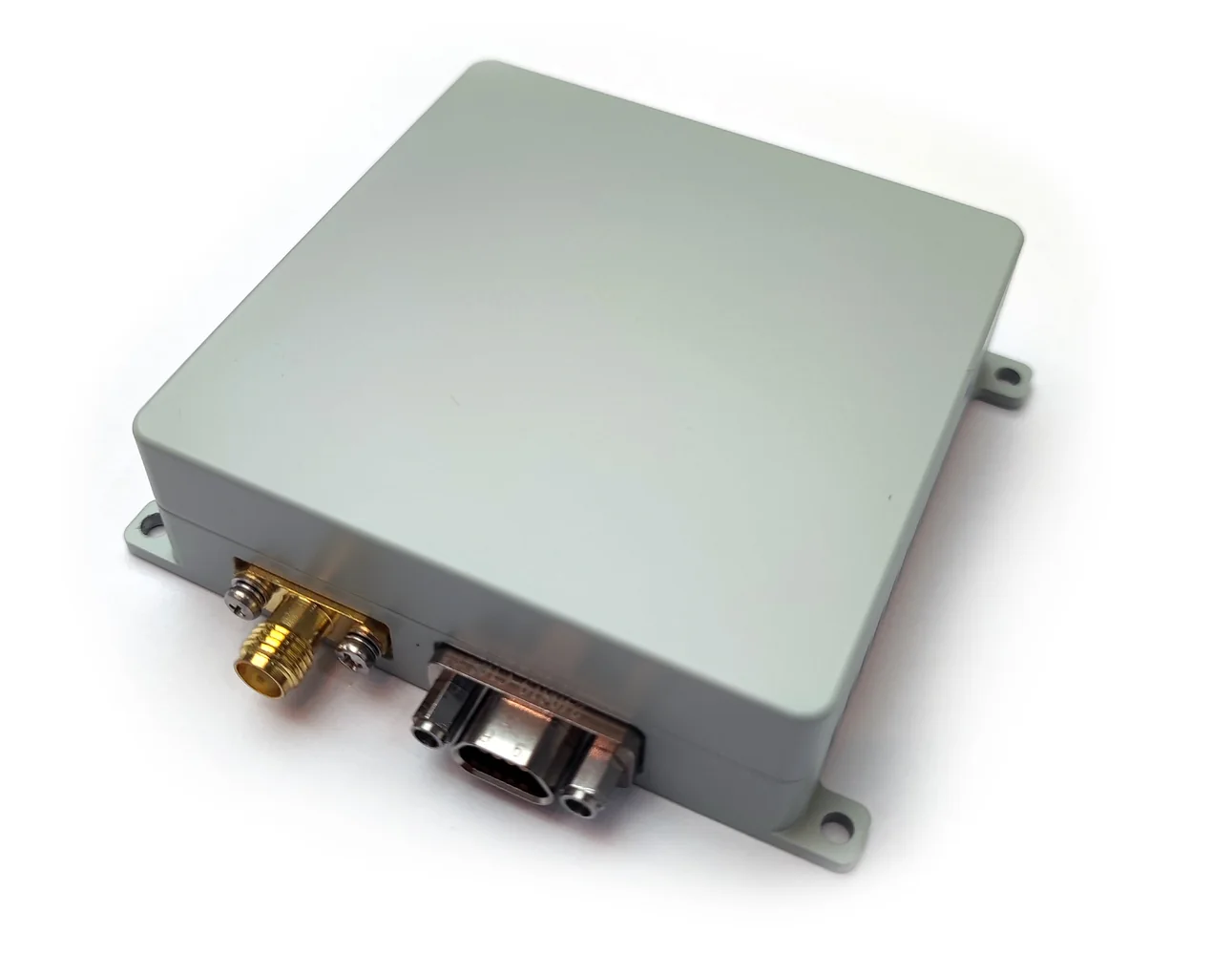
Compact 4-Channel Resilient PNT Terminal
Enhanced Dual-Frequency Resilient PNT Terminal
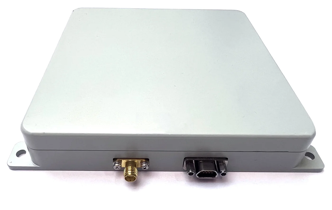
Anti-Jam + Anti-Spoof PNT Terminal
Next step
Share platform, protected bands, interfaces and project timing. Zhiyunlai will confirm a suitable starting configuration and the information needed for validation.