Constellation diversity
Match the protected frequencies to the vessel navigation architecture.
maritime GNSS anti-jam
Strengthen navigation continuity for autonomous vessels, workboats and other marine systems operating in congested spectrum.
Match the protected frequencies to the vessel navigation architecture.
Assess antenna placement, cabling, radome and nearby emitters.
Define bench and representative-platform checks before deployment.
Maritime GNSS resilience combines a protected receiver path with integrity monitoring, independent navigation inputs, alarms, defined degraded operation and tested recovery. A CRPA anti-jam front end can improve signal availability, but it does not by itself detect every spoofing event or replace vessel-level procedures.
| Review area | What to define | Evidence to request |
|---|---|---|
| GNSS system boundary | Antenna array, processing unit, receiver and protected output path | Block diagram, interfaces and stated measurement point |
| Interference scenario | Protected bands, waveform, level, geometry and simultaneous directions | Configuration-specific suppression and receiver-output results |
| Navigation integrity | Cross-checks, alarms and response to suspect position or time | Thresholds, alert latency, logs and bridge or autonomy-system action |
| Marine installation | Antenna location, cable loss, radome, nearby emitters and environment | Installation drawing, compatibility review and representative-platform check |
| Degraded operation | Independent references, fallback procedure and recovery criteria | Recorded outputs through loss, rejection and reacquisition of GNSS |
IMO, ICAO and ITU have jointly warned about increasing GNSS jamming and spoofing affecting maritime and other satellite-navigation users. See the IMO statement on satellite-navigation interference. NOVA products can protect the GNSS signal path; bridge procedures, integrity monitoring and independent navigation inputs remain vessel-level responsibilities. Use the anti-spoofing guide and testing framework to define separate, measurable evidence.
| Model | Published starting point | Protected bands | Mass and power | Anti-spoof |
|---|---|---|---|---|
| NOVA-T8 | 8-channel; three interference directions | B1 / L1 / G1 / E1 | ≤400 g; ≤12 W | No |
| NOVA-H7 | 7 elements; six interference directions | B1 / L1 / E1 / G1 | ≤1.2 kg; ≤25 W | No |
| NOVA-H16 | 16 elements; fifteen interference directions | B1 / L1 / E1 | ≤1.25 kg; ≤25 W | No |
Published values describe standard configurations, not guaranteed vessel-level results. Confirm the selected product, receiver path, environmental requirements and acceptance conditions in the quotation.
A CRPA front end can reduce interference before it reaches the GNSS receiver. The bridge or autonomy system should still monitor signal integrity, compare GNSS with independent navigation inputs and define alarms, degraded operation and recovery procedures.
No. Anti-jam processing addresses interference and signal availability. Anti-spoof protection addresses false or manipulated navigation signals. A maritime system exposed to both risks needs separate evidence and acceptance criteria for each.
Some configurations provide a protected RF path for a compatible external receiver, while others include a receiver or use a different host interface. Confirm protected bands, RF level, impedance, connector, power path, receiver compatibility and bridge or autonomy-system outputs before treating a terminal as a retrofit.
Define the interference condition, system boundary, monitored outputs, alarm threshold, degraded-mode action and recovery criteria. Use an authorized controlled-RF facility for repeatable tests, then verify mounting, cabling, nearby emitters and host-system behavior on a representative installation.
Provide the vessel or USV type, protected constellations and bands, GNSS receiver and output path, heading and navigation interfaces, antenna location, cable run, radome and nearby emitters, environmental requirements and measurable acceptance conditions.
Review sky visibility, the mounting surface or ground plane, separation from radar, satellite-communication and other high-power transmitters, plus cable type, length, loss, bend limits, connector sealing, grounding, radome and maintenance access. Then compare receiver status, signal-quality indicators, alarms and protected outputs with the bench baseline during representative vessel operation. Numeric clearances and gain budgets must follow the selected equipment, vessel arrangement and applicable installation requirements.
Use these models as an engineering shortlist, not as a substitute for a configuration review.
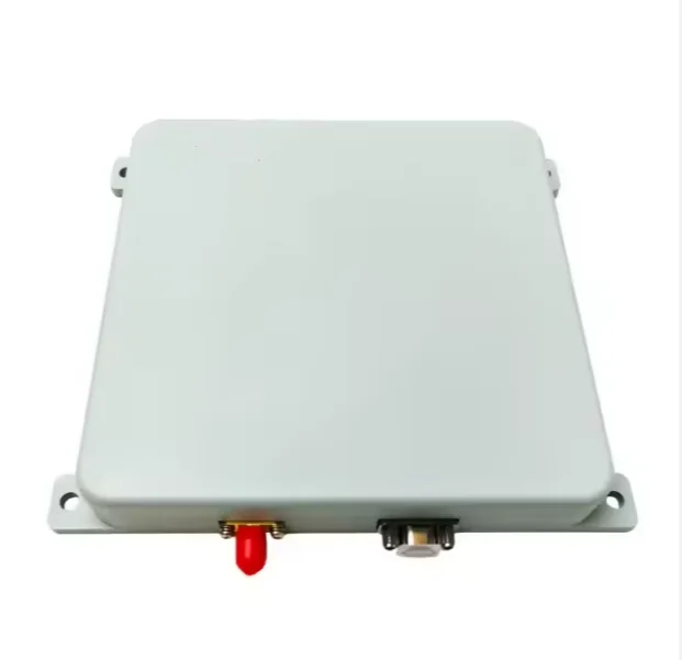
Tri-System Resilient PNT Terminal
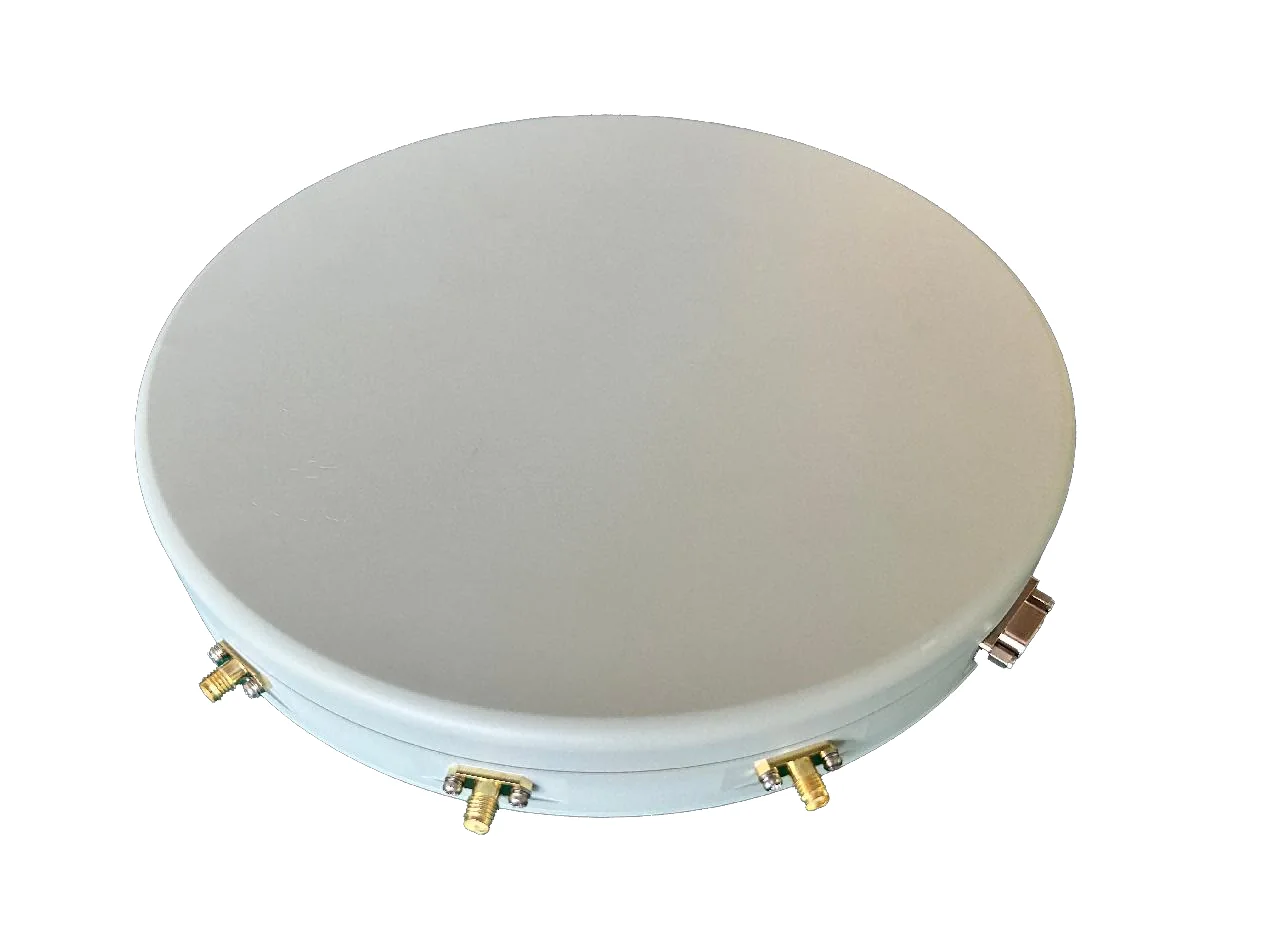
7-Element Multi-System Resilient PNT Terminal
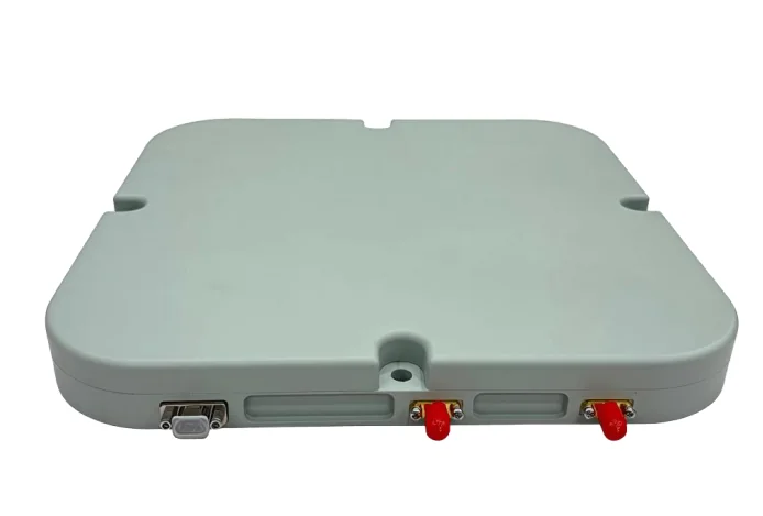
16-Element Multi-System Resilient PNT Terminal
Next step
Share platform, protected bands, interfaces and project timing. Zhiyunlai will confirm a suitable starting configuration and the information needed for validation.